Solar Panel Wiring: Series vs Parallel — A Visual Guide (2026)
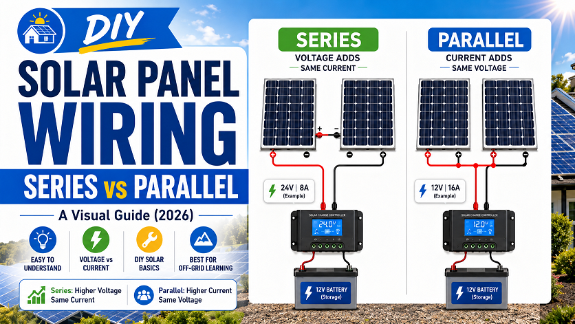
Series wiring adds panel voltages together while keeping current the same — ideal for MPPT charge controllers, long cable runs, and cold climates. Parallel wiring adds currents together while keeping voltage the same — better for shaded roofs and PWM controllers. For most DIY systems with 4+ panels in 2026, a series-parallel hybrid (2S2P or 3S2P) is the best approach — higher voltage for efficiency with better shade tolerance than pure series. The golden rule: never exceed your charge controller’s maximum input voltage, especially in cold weather when panel Voc rises.
The decision between wiring your solar panels in series or parallel is one of the first technical choices in any DIY solar build — and getting it wrong means either exceeding your charge controller’s voltage limit (a safety and equipment issue) or severely undersizing the voltage your system needs to charge efficiently.
The good news: the math is straightforward, the rules are consistent, and once you understand what changes (and what doesn’t) in each configuration, the right choice for your setup becomes obvious. This guide shows you everything with real numbers and visual diagrams.
Article 8 in the Shalkot DIY Solar Series
This article covers wiring configuration. For your panel count, see our Solar Panel Calculator. For the charge controller that receives this wiring, see our Best Charge Controller guide. For complete installation, see our DIY Installation Guide.
The One Rule That Governs Both Wiring Methods
Both wiring methods produce the same total wattage from your panels — the difference is how that power is packaged. Series gives you high voltage and lower current. Parallel gives you lower voltage and higher current. Your choice determines what charge controller you can use, how thick your cables need to be, and how sensitive your system is to shading.
Series Wiring — How It Works
To wire solar panels in series, connect the positive terminal of the first panel to the negative terminal of the next, and so on. Think of it like batteries in a flashlight — linking end to end. The voltage of each panel stacks up; the current stays the same as a single panel.
Cold Weather Warning for Series
Panel Voc rises in cold temperatures — up to 20% above the rated value. 4 panels with a 48V Voc in series = 192V at room temp, but could hit 230V on a cold winter morning. Always check your cold-weather Voc against your controller’s max input voltage before wiring in series.
When to Use Series Wiring
- Using an MPPT charge controller — MPPT controllers handle high voltage efficiently; this is the most common 2026 setup
- Long cable runs — higher voltage means lower current, which means thinner and cheaper wire with less voltage drop
- Cold climates — when you wire panels in series, the increased voltage provides more flexibility for charging even when the overall system output drops on cloudy winter days
- Unshaded roofs — series wiring works perfectly when no panel is ever partially shaded
- Reaching inverter minimum voltage — string inverters need a minimum operating voltage; series wiring reaches that threshold with fewer panels
Parallel Wiring — How It Works
When solar panels are wired in parallel, the positive terminal from one panel is connected to the positive terminal of another panel and the negative terminals of the two panels are connected together. All positives together, all negatives together. Current multiplies; voltage stays constant.
Parallel Needs Thick Wire and a Combiner Box
With 4 panels in parallel producing 40A, you need 6 AWG or even 4 AWG cable — heavier and more expensive than series wiring. You also need a combiner box or branch connectors to safely merge the parallel strings. Factor this into your budget.
When to Use Parallel Wiring
- Shaded or complex roofs — one shaded panel only reduces that panel’s contribution, not the whole array
- PWM charge controllers — parallel solar arrays are ideal when you want a low voltage system using a lower-cost PWM controller that needs panel voltage to match battery voltage
- When series would exceed controller voltage — if your panels’ Voc × number of panels exceeds your controller’s max input, parallel keeps voltage safe
- 12V battery systems with panels already at 18–20V — single panels already exceed 12V charging requirement; parallel adds current without over-voltaging
Series vs Parallel: Side-by-Side Comparison
Using the same four 400W panels (40V / 10A each) wired differently:
| Factor | Series | Parallel | Winner |
|---|---|---|---|
| Voltage output | High (panels × Vmp) | Low (single panel Vmp) | Depends on controller |
| Current output | Low (single panel Imp) | High (panels × Imp) | Series (thinner wire) |
| Wire size required | Thinner — 10 AWG typical | Thicker — 6–4 AWG for 4+ panels | Series |
| Wire cost for long runs | Significantly lower | Significantly higher | Series |
| Shade tolerance | Poor — one shaded panel drags whole string | Good — shaded panel only reduces its contribution | Parallel |
| Charge controller type | MPPT required | PWM or MPPT | Parallel (more options) |
| Low-light / cloudy charging | Better — higher voltage starts charging earlier | Can struggle to reach minimum charge voltage | Series |
| Cold weather voltage risk | Voc rises in cold — must verify controller max V | No voltage rise risk | Parallel |
| Wiring complexity | Simpler — daisy-chain connection | Needs combiner box or branch connectors | Series |
| Best for most 2026 DIY systems | With MPPT controller, unshaded roof | Shaded sites, small systems, PWM | Series-parallel hybrid |
The Shade Problem — How Each Configuration Handles It
Shade is the most critical real-world factor in choosing your wiring configuration. If shade covers a single panel of your series array, it will bring down the whole system’s power output. Each panel in a series connection is critical.
Here is the exact math for a 4-panel 400W system when one panel is 50% shaded:
The Solutions for Shaded Series Strings
Bypass diodes: Most modern solar panels include built-in bypass diodes in their junction boxes that partially bypass shaded cells — but they do not fully solve the series shade problem.
Power optimizers (SolarEdge): Add a DC optimizer to each panel that makes each panel operate independently within the series string. Shade on one panel no longer limits the others. Cost: ~$50–$80 per panel.
Microinverters (Enphase): Each panel has its own microinverter and operates 100% independently — the ultimate shade solution. Cost: $150–$250 per panel.
Series-parallel hybrid: Wire in 2S2P or 3S2P — shade affects only one 2-panel string, limiting loss to 25% rather than 50%.
Series-Parallel Hybrid — The Best of Both Worlds
For most off-grid systems with four or more panels, a series-parallel (2S2P) hybrid configuration offers the best balance of efficiency, shade tolerance, and cable management.
In a hybrid configuration, you wire panels in series first (creating “strings”), then wire those strings in parallel. This gives you a mid-range voltage (better than pure parallel for MPPT efficiency) with only half the shade sensitivity of pure series.
2 strings of 2 panels
Best for most 4-panel builds
2 strings of 3 panels
Common off-grid cabin
3 strings of 2 panels
Better shade tolerance
2 strings of 4 panels
Check controller max V!
4 strings of 2 panels
Best shade tolerance
3 strings of 3 panels
Balanced configuration
How to Wire 2S2P Step by Step
1. Wire Panel 1 (+) to Panel 2 (−) — this is String A (80V / 10A).
2. Wire Panel 3 (+) to Panel 4 (−) — this is String B (80V / 10A).
3. Connect String A (+) to String B (+) → this becomes your array (+).
4. Connect String A (−) to String B (−) → this becomes your array (−).
5. Connect array (+) and (−) to your charge controller’s PV input terminals.
Result: 80V at 20A into the controller.
Charge Controller Compatibility
Your wiring configuration determines which charge controller you can use — and this is one of the most important compatibility checks before finalizing your design.
| Wiring Config | Typical Array Voltage | Controller Required | Why |
|---|---|---|---|
| 1 panel (single) | 40–48V Voc | PWM or MPPT | Single panel voltage close to battery — PWM is viable for 12V systems |
| 2 panels in series (2S) | 80–100V Voc | MPPT required | Too high for PWM — MPPT converts extra voltage into charging current |
| 2 panels in parallel (2P) | 40–48V Voc | PWM or MPPT | Same voltage as single panel — PWM viable, MPPT preferred |
| 4 panels 2S2P | 80–100V Voc | MPPT — 100V max input | 80V nominal; Voc in cold could hit 96V — Victron 100/50 handles this safely |
| 4 panels in series (4S) | 160–200V Voc | MPPT — 150V+ required | Needs a 150V or 200V input controller; Victron 150/35, EPEver 4210AN |
| 6 panels 3S2P | 120–144V Voc | MPPT — 150V input required | Must use Victron 150/xx or EPEver Tracer — standard 100V controllers will be exceeded |
Never Exceed Your Controller’s Maximum PV Input Voltage
Exceeding your charge controller’s maximum PV input voltage — even briefly on a cold morning — permanently damages the controller. This is the most common and most expensive mistake in DIY solar wiring. Always calculate your array’s open-circuit voltage (Voc, not Vmp) multiplied by all panels in series, then apply a cold-weather correction factor of 1.15–1.25 depending on your climate. This cold-corrected Voc must remain below your controller’s rated maximum input voltage. If you are near the limit, use one fewer panel in series or step up to a 150V-rated controller.
Which Charge Controller for Your Wiring Config?
For 2S or 2S2P configurations with up to 100V array voltage: Victron SmartSolar 100/50 or Renogy Rover 40A handle this perfectly. For 3S2P or 4S configurations reaching 120–150V: you need the Victron SmartSolar 150/35 or EPEver Tracer 4210AN. See our full Charge Controller Guide for detailed comparisons.
Wire Gauge Guide for Series and Parallel
Wire gauge is determined by the current flowing through the wire — add a 25% safety factor. Series strings = single panel Isc; parallel arrays = sum of all Isc values. Keep voltage drop under 3%.
The 3% Voltage Drop Rule
Keep total voltage drop from panels to charge controller under 3%. Longer cable runs require thicker wire. For a series string carrying 10A over 50 feet of round-trip distance, 10 AWG PV wire keeps you well under 3% drop. For the same 50 feet in a parallel array carrying 40A, you need 4 AWG to stay under 3%. When in doubt, go one gauge thicker — the performance improvement in your solar harvest over 10+ years far outweighs the added cable cost.
Which Wiring Method Is Right for You?
Not Sure How Many Panels You Need?
Use our Solar Panel Calculator first — it tells you your system size, which determines how many panels you’ll be wiring and what configuration makes most sense.
Frequently Asked Questions
Should I wire solar panels in series or parallel?
Wire solar panels in series when using an MPPT charge controller (which converts high voltage into optimal charging current), when you have long cable runs, or in cold climates where high panel voltage is an advantage. Wire in parallel when panels face partial shade at different times, when using a PWM controller that needs panel voltage to match battery voltage, or when you want each panel to operate independently. For most DIY systems with 4+ panels and an MPPT controller, a 2S2P series-parallel hybrid gives the best balance.
What happens when you wire solar panels in series?
When solar panels are wired in series, the voltage of the panels adds together, but the amperage remains the same. For example, two 400W panels rated at 40V and 10A each wired in series produce 80V at 10A — still 800W total. Series wiring requires an MPPT charge controller and produces thinner wire requirements due to lower current. The major downside is shade sensitivity: one shaded panel significantly reduces output for the entire string.
What happens when you wire solar panels in parallel?
Wiring solar panels in parallel causes the amperage to increase, but the voltage remains the same. Two 400W panels at 40V/10A wired in parallel produce 40V at 20A — still 800W total. Parallel wiring is more shade-tolerant because a shaded panel only reduces that panel’s current contribution — the others continue at full output. The main downside is higher amperage requiring thicker, more expensive cable.
Can you mix series and parallel wiring for solar panels?
Yes — and for most 4+ panel systems this hybrid approach is the recommended configuration in 2026. Wire panels into series strings first, then connect those strings in parallel. For example, 4 panels wired 2S2P (two strings of two panels each in parallel) produces 80V at 20A = 1,600W. This gives you higher voltage for MPPT efficiency with better shade tolerance than pure series wiring.
Does shading one solar panel affect the whole series string?
Yes, significantly. If shade covers a single panel of your series array, it will bring down the whole system’s power output. In a 4-panel series string, one panel shaded to 50% output limits the entire string to 50% current — cutting your total output in half. This is why shaded roofs benefit from parallel or hybrid wiring, or from adding power optimizers or microinverters that make each panel operate independently.
Do I need an MPPT or PWM charge controller for series wiring?
Series wiring almost always requires an MPPT charge controller. When panels are wired in series, the array voltage — often 80–160V — far exceeds your 12–48V battery voltage. A PWM controller cannot handle this mismatch — it clamps the high panel voltage down to battery level, wasting all the excess voltage as heat and losing 25–40% of your solar harvest. An MPPT controller converts that excess voltage into additional charging current, delivering nearly the full panel output. The only exception where PWM might work is when panels are wired in parallel and their single-panel voltage is close to your battery voltage.
What wire gauge do I need for series vs parallel solar wiring?
Wire gauge is determined by the current in the circuit, not the voltage. In a series string, current equals one panel’s Isc — typically 10–12A for a 400W panel — so 10 AWG PV wire handles most series configurations adequately. In a parallel array, current equals the sum of all panels’ Isc values — four panels at 10A each = 40A, which requires 6 AWG or 4 AWG for safe temperature ratings and to keep voltage drop under 3%. Always size wire based on the actual current plus a 25% safety factor, not the panel’s rated wattage.
Continue Your DIY Solar Build
- Off Grid Benchmark — Solar Panel Wiring: Series vs Parallel Guide (2026), April 2026
- Solar Reviews — Do You Wire Solar Panels Series or Parallel?
- Battle Born Batteries — Solar Panels in Series or Parallel: Which Is Better?, August 2025
- Solar Energy Solutions of America — Wiring Series vs Parallel Solar Panels: Key Differences, September 2025
- Anker SOLIX — Series vs Parallel Solar Panels: Wiring Methods and When to Use Each, November 2025
- Sungold Solar — Solar Panels Series vs Parallel: Understanding and Differences, May 2025
- Haina Solar — Series vs Parallel Solar Panel Wiring Methods Explained, December 2025
5 thoughts on “Solar Panel Wiring: Series vs Parallel — A Visual Guide (2026)”